[Home] | [lesson1_1] | [lesson1_2] | [lesson1_3] | [lesson1_4] | [lesson1_5] | [Assignment]
Course Notes:
(Note the difference in handout voltages shown – USA=110v Aust=220 200/240V
ATX power supplies as well as having a direct 3.3v lead to supply the CPU have a power on and 5v standby signal lead.
Some power supplies are designed to have some sort of loading on the +12v leads – This is usually some sort of drive (eg. Hard drive) Some power supplies won’t work without the lead connected. With others, damage can occur to power supply if they are switched on without this load on.
Single cord to the power unit – older computers have a ‘pass through’ connector that was used by the monitor.
On the older machines the on/off switch was
on the actual power supply box. On later machines (AT form factor ) this was
moved to the front of the computer and was a mechanical connections or the 240v
power leads were extended to a switch on the case. ATX form factor power supplies
use an electronic switch, which connects to the motherboard and acts like a
reset switch. When the button is pressed it signals the motherboard (requests)
the on/off action that in turn either turns the power supply on or off.
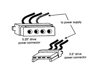
Drive
Connectors
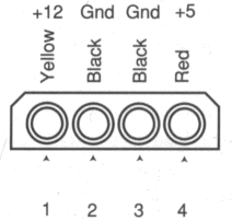
The following are pin numbering for the two
types of connectors

Disk Drive Power Connector Pinout:

|
Pin |
Wire Colour |
Signal |
|
1 |
Yellow |
+12V |
|
2 |
Black |
Gnd |
|
3 |
Black |
Gnd |
|
4 |
Red |
+5V |
Motherboard Connectors
Typical PC/XT and
AT Power Supply Connections:
|
Connector |
AT Type |
PC/XT Type |
|
P8-1 |
Power Good (+5V) |
Power Good (+5V) |
|
P8-2 |
+5V |
Key (No Connect) |
|
P8-3 |
+12V |
+12V |
|
P8-4 |
-12V |
-12V |
|
P8-5 |
Ground (0) |
Ground (0) |
|
P8-6 |
Ground (0) |
Ground (0) |
|
P9-1 |
Ground (0) |
Ground (0) |
|
P9-2 |
Ground (0) |
Ground (0) |
|
P9-3 |
-5V |
-5V |
|
P9-5 |
+5V |
+5V |
|
P9-6 |
+5V |
+5V |
|
P10-1 |
+12V |
+12V |
|
P10-2 |
Ground (0) |
Ground (0) |
|
P10-3 |
Ground (0) |
Ground (0) |
|
P10-4 |
+5V |
+5V |
|
P11-1 |
+12V |
+12V |
|
P11-2 |
Ground (0) |
Ground (0) |
|
P11-3 |
Ground (0) |
Ground (0) |
|
P11-4 |
+5V |
+5V |
|
P12-1 |
+12V |
-- |
|
P12-2 |
Ground (0) |
-- |
|
P12-3 |
Ground (0) |
-- |
|
P12-4 |
+5V |
-- |
|
P13-1 |
+12V |
-- |
|
P13-2 |
Ground (0) |
-- |
|
P13-3 |
Ground (0) |
-- |
|
P13-4 |
+5V |
-- |
ATX Power Supply Connections:
|
Signal |
Pin |
Pin |
Signal |
|
3.3V |
11 |
1 |
3.3V |
|
-12V |
12 |
2 |
3.3V |
|
GND |
13 |
3 |
GND |
|
Pwr_On |
14 |
4 |
5V |
|
GND |
15 |
5 |
GND |
|
GND |
16 |
6 |
5V |
|
GND |
17 |
7 |
GND |
|
-5V |
18 |
8 |
Power Good |
|
5V |
19 |
9 |
5V_Standby |
|
5V |
20 |
10 |
12V |
Currently in the industry there are eight power supply form factors. Each of these form factors can have various amounts of configurations and power output levels.
|
PC / XT |
LPX |
Each of these supplies are available in numerous different configurations and power output levels.
When IBM introduced the XT, it used the same basic power supply shape as the original PC, except that the new XT supply had more than double the power output capability. Because they were identical in both external appearance and the type of connectors used, you could easily install the better XT supply as an upgrade for a PC system. psxt.gif
When IBM later introduced the AT desktop system, it created a larger power supply that had a form factor different from the original PC/XT. This system was rapidly cloned as well, and to this day still represents the basis for most IBM compatible designs. The power supply used in these systems is called the AT/Desktop style power supply. psatdesktop.gif
This form factor is identical to the AT/Desktop except for the power switch location. Most AT/Desktop systems required that the power switch be located right on the power supply itself, while most AT/Tower systems use an external switch attached to the power supply through a short 4-wire cable. psattower.gif
This form factor is also based on the full AT style except that it is shortened on one dimension. This supply can be used in the larger AT style chassis, however, the full six AT/Tower power supply will not fit into the Baby-AT chassis. psbabyat.gif
This type of form factor was designed to meet to needs of the slim line computers that was being made. The slimline motherboard contained a riser card for all of the expansion slots that makes the system very low in height. Some full sized AT Desktop and Tower cases today are designed to also accept the slimline form factor power supply. psslimline.gif
This form factor is one of the newest on the market. It resembles the slimline but has several major differences. One difference is the fan location and the reverse air flow. The fan is now mounted along the inner side of the supply and blows air across the motherboard and drawing it in from the outside at the rear. This will also keep the computer much cleaner since air, dust, and dirt are not trying to be sucked in every hole in the case and drives. Also, if the computer operates in harsh environments a simple air filter could be applied to the cooling fan to keep out more dirt. Another new feature is the power connector that connects the power supply to the motherboard. One of the major drawbacks to the AT style is the two connectors that connect the power supply to the motherboard. These connectors could be swapped with each other and would destroy the motherboard. The new ATX power supply has one 20 pin connector that is keyed and is virtually impossible to connect wrong to the motherboard. And finally, there are three more signals added to the connector that connects the power supply and the motherboard. These new signals are a 3.3 V supply which eliminates regulators on the motherboard, Power_On signal which can shut down the computer through software, and 5 V_Standby signal which is always active, giving the motherboard a limited source of power even when off. psatx.gif
Cooling fans are
used on all power supplies as well as extra fans now for both the cases and
CPUs.
Normally on a AT power supply the fan blows outward and on ATX the fan blows inward
Power supply ratings are usually supplied by the manufacturers in a technical reference manual or most of the time a sticker mounted on top or side of the power supply. If the total wattage is not listed then you can calculate what it is by this formula:
Wattage = Voltage x Amperage
By multiplying the voltage by the amperage available at each output then adding them up, you can calculate the total capable output wattage of the supply. The following table shows some data from various manufacturers that advertise the total wattage ratings but when you calculate them out and add them up it can be quite different especially in higher wattage ratings.
|
Specified Output Wattage |
100W |
150W |
200W |
250W |
300W |
375W |
450W |
|
Output Current x +5V |
10.0 |
15.0 |
20.0 |
25.0 |
32.0 |
35.0 |
45.0 |
|
Output Current x -5V |
0.3 |
0.3 |
0.3 |
0.5 |
1.0 |
0.5 |
0.5 |
|
Output Current x +12V |
3.5 |
5.5 |
8.0 |
10.0 |
10.0 |
13.0 |
15.0 |
|
Output Current x -12V |
0.3 |
0.3 |
0.3 |
0.5 |
1.0 |
0.5 |
1.0 |
|
Calculated output wattage |
97.1 |
146.1 |
201.1 |
253.5 |
297.0 |
339.5 |
419.5 |
When selecting a power supply a minimum of 200W should be obtained. Generally a 250W power supply will give the user enough extra power to allow for new hardware to be installed into the computer.
Set the multimeter
to the require DC voltage range (e.g. 0-20).
Connect one of the
test probes of the multimeter to ground (earth) and the other to the voltage
lead.
The readings should
be within the following tolerance readings
*Note remember to
load power supplies
Surge Protectors
– work like a fuse. They take the damage not the computer. There are two types,
ones that can be reset and ones that once they blow must be discarded.
Power conditioners
– include surge protection in their construction but are mainly used for line
conditioning in that they filter out line noise and provide a steadier voltage.
UPS (Uninterruptible
Power Supply) – these provide continuous no-break power supply to a computer. They
rely on a battery backup to provide the power source while the mains power is
off. The size of the battery usually determines the amount of time these units
will provide power. Usually most range from 10 to 30 minutes.
SPS (Standby Power
Supply) – These power supplies
switch over to another source of power after a power break. There is usually
some sort of break to the power supplied to computers while this system switches
in.